

Data Logger and Telemetry System for Model Airplane – 1, let’s beggin!
Since model airplanes fly according to visual flight rules, they don’t have any tracking, control and security systems. Lack of these systems may lead to destroy the aircraft and the area which it is flying. The aim of the designed telemetry system is to transmit the aircraft data to the ground station and to provide observing the momentary results of the aircraft. Thus, when aircraft goes into dangerous station, pilot can observe the sensor values and may change the position of the aircraft so that the probability of the crashing the aircraft is decreased. Individually designed system is not included in model airplanes.
This system may be easily integrated to the model airplanes with the benefits of portability, small sizes and small weights. Telemetry system consists of two separate modules. Aircraft module provides to analyze position, velocity, pressure, IMU sensors in the aircraft and send the signals to the ground station. Ground control module shows the incoming signals to the pilot.
Aircraft telemetry and data logger system aims to improve visual capabilities between aircraft and pilot.
Aircraft telemetry and data logger system aims to improve visual capabilities between aircraft and pilot. System basically consists of two modules. While aircraft module is responsible to process sensors and transmit the relevant information to the ground, ground control computer is responsible to log the information and show this information to the user.
Aircraft module interacts with the sensor via microprocessor. Arduino Mega development board is used as microprocessor board. This board is small in size and has large GPIO and support different communication protocols. It has one I2C and four serial communication port. Sensors are communicated to the board via I2C protocol. I2C protocol enables to connect multi sensors in a single pin.
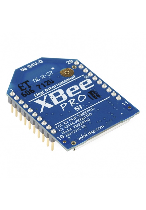
This connection is established by giving the addresses of each sensor. So that sensors are easily connected. IMU, pressure, temperature sensors are connected only two pin (SDA,SDL) of the arduino mega development board by using I2C protocol. GPS sensor supports serial communication. GPS uses serial port 1 of the board and system communicates with the ground station in serial port 2. Wireless communication between aircraft and ground control computer is archived by xbee pro modules. These modules have a range up to 10km with the 300mW power option. Xbee modules can be programmed by AT command or a program can be used to change the values in it. It has baud rate, power and mode selections. Xbee modules use the zigBee standard to communicate. ZigBee is used in low data rate, long battery life and secure networking applications. [1]
Ground control computer (GCC) is responsible to show and log the data which is received from aircraft module. It has the ability to show the data with respect to time. User can see exact time of the flying, start and stop the communication, report the database values into .pdf or .xls format, observe the aircraft connection in the map if the internet is available.
In this article, we talked about Data Logger and Telemetry System for Model Aircraft. You can reach my other article from the link.
References:
[1] http://en.wikipedia.org/wiki/ZigBee