
Data Logger and Telemetry System for Model Airplane – 4, let’s beggin!
GPS is examined in two parts. GPS receiver is the first part of it. It provides to take GPS signal from the satellite and send the information from its serial port. Its internal serial port sends the data through tx port. The data is sent via NMEA format so that it is needed to decode the NMEA format. After that in second part, in order to decode the signal NMEA format is introduced.
GPS Receiver
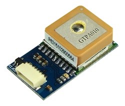
In the project, the MediaTek MT3329 GPS module is used. It can be seen in figure 1. The MediaTek-3329 is an ultra-compact POT (Patch on Top) GPS Module. This POT GPS receiver provides a solution that is also high in position and speed accuracy performances, with high sensitivity and tracking capabilities in urban conditions. The module can support up to 66 channels and is designed for a small-form-factor device.
Technical Specifications of MT3329 GPS module is [2]:
- Dimension:16mm x 16mm x 6mm
- Cold Start is under 35 seconds (Typical)
- Warm Start is under 34 seconds (Typical)
- Hot Start is under 1 second (Typical)
- Low Power Consumption:48mA @ acquisition, 37mA @ tracking
- Low shut-down current consumption:15uA, typical
- DGPS(WAAS, EGNOS, MSAS) support (optional by firmware)
- USB/UART Interface
- Weight: 0.3oz; 8 g
- Operating Temperature: -40 °C to 85 °C
- Storage Temperature: -50 °C to 90 °C
- Operating Humidity: 5% to 95% (no condensing)
- Mounting SMD Type: 10 Pin
- Altitude Maximum: 18,000m
- Velocity Maximum: 515m/s
- Acceleration Maximum: 4G
- Signal Output: 8 data bits, no parity, 1 stop bit
- Available Baud Rates Default: 9600 bps (4800/9600/38400/57600/115200 bps by customization)
Protocols: NMEA 0183 v3.01 (Default: GGA, GSA, GSV, RMC, VTG) MTK NMEA Command
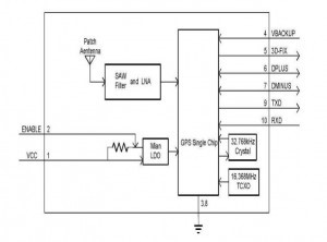
The block diagram of MT3329 is illustrated in figure 2. As it can be seen from the figure there are ten ports which provides the exact communication between GPS module and user. The detailed information about the I/O pins is explained in the following table1:
| Pin Name | I/O | Description | |
| 1 | VCC | PI | Main DC power input |
| 2 | ENABLE | I | High active, or keep floating for normal working |
| 3 | GND | P | Ground |
| 4 | VBACKUP | PI | Backup power input |
| 5 | 3D-FIX | O | 3D-fix indicator |
| 6 | DPLUS | I/O | USB port D+ |
| 7 | DMINUS | I/O | USB port D- |
| 8 | GND | P | Ground |
| 9 | TXD | O | Serial data output of NMEA |
| 10 | RXD | I | Serial data input for firmware update |
NMEA Format
GPS receiver communication is defined within this specification. Most computer programs that provide real-time position information understand and expect data to be in NMEA format. This data includes the complete PVT (position, velocity, time) solution computed by the GPS receiver. The idea of NMEA is to send a line of data called a sentence that is totally self-contained and independent from other sentences. There are standard sentences for each device category and there is also the ability to define proprietary sentences for use by the individual company.
All of the standard sentences have a two letter prefix that defines the device that uses that sentence type. (For GPS receivers the prefix is GP.) which is followed by a three-letter sequence that defines the sentence contents. In addition NMEA permits hardware manufactures to define their own proprietary sentences for whatever purpose they see fit. All proprietary sentences begin with the letter P and are followed with 3 letters that identify the manufacturer controlling that sentence. For example, a Garmin sentence would start with PGRM and Magellan would begin with PMGN.
An important message in order to keep communication is shown below.
$GPRMC,064951.000,A,2307.1256,N,12016.4438,E,0.03,165.48,260406,3.05,W,A*2C
In this sentence $GPRMC represent one of the 19 interpreted sentences and it is protocol header. RMC stands for Recommended Minimum Specific GPS/Tracking Data in GPRMC. 064951.000 indicates real-time in HH.MM.SS.SSS. Namely, the exact time is 06:49:51.000. A means data is valid. If this data is not valid data A replace with V which indicates that data is not valid. 2307.1256 shows the latitude information in DD.MM.MMM format. Next, N indicates North which also could be S for the south.
Similarly, 12016.4438 shows longitude and E for East. E also could be replaced with W for West. 0.03 indicates the speed over the ground in knots. 165.48 shows the course value over the ground in degree. 260406 shows the date on which day information is sent. 3.05, W shows the magnetic variation in degree but it should be noted that this needs the customization service. The mode of the message is represented by a letter of A. A stands for automatic D for differential, E for estimated. *2C is the checksum. Checksum always starts with a star before it. To sum up, we can decode the information like table 2:
| Time | 06:49:51.000 |
| Latitude | 23 degree 07.1256 minute north |
| Longitude | 120 degree 16.4438 minute east |
| Speed over ground | 0.03 knot |
| Course over ground | 165.48 degree |
| Date | 26.04.2006 |
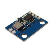
Static Pressure Sensor
Bosch’s BMP085 is a rock-solid barometric pressure sensor. It features a measuring range of anywhere between 30,000 and 110,000 Pa. ‘Pa’ meaning the Pascal unit, which you’ll probably more often see converted to hPa (hectoPascal), equal to 100 Pa, or kPa (kiloPascal), which is 1000 Pa. As a bonus, the BMP085 also provides a temperature measurement, anywhere from 0 to 65°C
The BMP085 has a digital interface, I2C to be specific. This means there may is a bit more overhead to get it talking to a microcontroller, but in return, data is returned that is much less susceptible to noise and other factors that may hamper an analog signal. I2C is a synchronous two-wire interface, the first wire, SDA, transmits data, while a second wire, SCL, transmits a clock, which is used to keep track of the data. If Arduino is used to talk to the BMP085, the Wire library will conveniently take care of most of the work in communicating with the sensor.
The BMP085 have some advantages which are given in below .
- Moderately high resolution in “ultra-high” mode, perfectly adequate for most applications (but not quite up to Bosch’s marketing)
- Fast enough for most applications (up to 130 or 222 Hz in two lower resolution modes)
- Low cost, compared to precision barometric pressure sensors
- Flexible has several modes of resolution and update rates
- Fast response, no hysteresis
- All digital uses I2C interface
- Also provides temperature
- Easy to wire up
- Very small size, low power
The BMP085 have some disadvantages which are given in below.
- A complex calibration routine must be run for each sample (however it uses integer math and the execution time is trivial on embed)
- Doesn’t have a continuous mode of operation, so you need to run a ticker on the mbed to get samples at fixed rates
- Doesn’t have a hose port, so if you need one you’ll have to make an adapter
- No option for changing I2C bus address, however, the datasheet has a trick for using two on the same I2C bus
- Should have options for even more oversampling than given by the “ultra-high” resolution mode
In this article, we talked about Data Logger and Telemetry System for Model Aircraft. You can reach my other article from the link.