
Data Logger and Telemetry System for Model Airplane – 3, let’s beggin!
Gyroscope
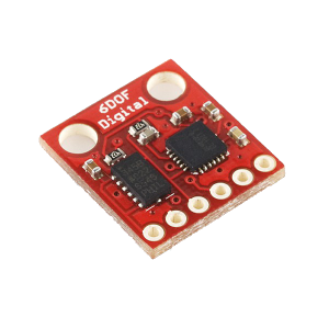
Gyroscopes function differently depends on their type. Traditional spinning gyroscopes work on the basis that a spinning object that is tilted perpendicularly to the direction of the spin will have a precession. The precession keeps the device oriented in a vertical direction so the angle relative to the reference surface can be measured. Optical gyroscopes are most commonly ring laser gyroscopes. These devices send two lasers around a circular path in opposite directions. If the path spins, a phase shift can be detected since the speed of light always remains constant. Usually, the rings are triangles or rectangles with mirrors at each corner. Optical gyroscopes are a great improvement to the spinning mass gyroscopes because there is no wear, greater reliability and smaller size and weight [1]. Even after the introduction of laser ring gyroscopes, a lot of properties were desired. MEMS vibrating mass gyroscopes aimed to create smaller, more sensitive devices. In this project, MEMS gyroscopes are used. MEMS gyro is shown below.
Gyroscopes measure the rotation around the axes. For example, a 2-axes gyroscope will measure the rotation around X and Y axes. The logic of the gyroscopes is explained below. [2]
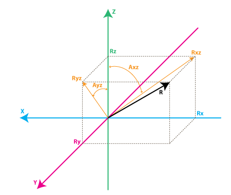
- Rxz – is the projection of the inertial force vector R on the XZ plane
Ryz – is the projection of the inertial force vector R on the YZ plane - From the right-angle triangle formed by Rxz and Rz, using Pythagorean Theorem we get:
- Rxz^2 = Rx^2 + Rz^2, and similarly:
- Ryz^2 = Ry^2 + Rz^2
Also:
R^2 = Rxz^2 + Ry^2, this can be derived from Eq.1 and above equations, or it can be derived from right-angle triangle formed by R and Ryz
R^2 = Ryz^2 + Rx^2
Instead the angle will be defined between the Z axis and Rxz, Ryz vectors as follows:
Axz – is the angle between the Rxz (projection of R on XZ plane) and Z axis
Ayz – is the angle between the Ryz (projection of R on YZ plane) and Z axis
The gyroscope measures the rate of changes of the angles defined above. In other words, it will output a value that is linearly related to the rate of change of these angles. To explain this let’s assume that the rotation is measured around axis Y (that would be Axis angle) at time t0, and it is defined as Axz0, next this angle is measured at a later time t1 and it was Axz1. The rate of change will be calculated as follows:
RateAxz = (Axz1 – Axz0) / (t1 – t0).
If the Axis is expressed in degrees, and time in seconds, then this value will be expressed in deg/s. This is what a gyroscope measures.
In practice, a gyroscope (unless it is a special digital gyroscope) will rarely give you a value expressed in deg/s. Let’s introduce the ADC to deg/s conversion formula for gyroscope
(we assume we’re using a 10bit ADC module , for 8bit ADC replace 1023 with 255, for 12bit ADC replace 1023 with 4095).
- RateAxz = (AdcGyroXZ * Vref / 1023 – VzeroRate) / Sensitivity (Eq.1)
- RateAyz = (AdcGyroYZ * Vref / 1023 – VzeroRate) / Sensitivity
AdcGyroXZ, AdcGyroYZ – is obtained from the ADC module and they represent the channels that measure the rotation of projection of R vector in XZ respectively in YZ planes, which is equivalent to saying rotation was done around Y and X axes respectively.
Vref – is the ADC reference voltage it is used 3.3V in the example and the project.
VzeroRate – is the zero-rate voltage, in other words, the voltage that the gyroscope outputs when it is not subject to any rotation,
Sensitivity – is the sensitivity of gyroscope it is expressed in mV / (deg / s) often written as mV/deg/s, it basically tells how many mV will the gyroscope output increase, if the rotation speed is increased by one deg/s.
Let’s take an example, suppose our ADC module returned following values:
- AdcGyroXZ = 500
- AdcGyroXZ = 300
Using the above formula:
- RateAxz = (500* 3.3V / 1023 – 1.23V) / ( 0.002V/deg/s) =~ 807 deg/s =~ 87.42
- RateAyz = (300 * 3.3V / 1023 – 1.23V) / ( 0.002V/deg/s) =~ 484 deg/s=~ 124
In other words, the device rotates around the Y-axis (or it rotates in XZ plane) with a speed of 87.42 deg/s and around the X-axis (or it rotates in YZ plane) with a speed of 124 deg/s. If the sign is negative it simply means that it rotates the inverse direction.
Magnetic Compass
A magnetometer is an instrument used to measure the strength and/or direction of the magnetic field in the vicinity of the instrument. Earth’s magnetism varies from place to place due to the differing nature of rocks or the interaction between charged particles from the sun and the magnetosphere.
Magnetometers are used in geophysical surveys because they can measure the magnetic field variations caused by rocks and mineral deposits.
They are used in directional drilling for oil or gas to detect the azimuth of the drilling tools near the drill bit. They are most often paired up with accelerometers in drilling tools so that both the inclination and azimuth of the drill bit can be found. Magnetometers are also used to map archaeological sites, shipwrecks and other buried or submerged objects. Magnetometers are also used by satellites like goes to measure the magnitude and direction of the earth’s magnetic field.
Magnetometers are very sensitive and can give an indication of possible auroral activity before one can see the light from the aurora. A grid of magnetometers around the world constantly measures the effect of the solar wind on the earth’s magnetic field.
In the project, The Honeywell HMC5883L magnetometer is used. The Honeywell HMC5883L is a multi-chip module designed for low-field magnetic sensing with a digital interface for applications such as low-cost compassing and magnetometry.
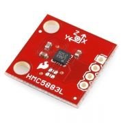
İncludes state-of-the-art, high-resolution HMC118X series magneto-resistive sensors plus an ASIC containing amplification, automatic degaussing strap drivers, offset cancellation, and a 12-bit ADC that enables 1° to 2° compass heading accuracy. The I2C serial bus allows for an easy interface. Applications for the HMC5883L include Mobile Phones, Netbooks, Consumer Electronics, Auto Navigation Systems, and Personal Navigation Devices.
The HMC5883L utilizes Honeywell’s Anisotropic Magnetoresistive (AMR) technology that provides advantages over other magnetic sensor technologies. These anisotropic, directional sensors feature precision in-axis sensitivity and linearity. These sensors’ solid-state construction with very low cross-axis sensitivity is designed to measure both the direction and the magnitude of Earth’s magnetic fields, from milli-gauss to 8 gausses. Honeywell’s Magnetic Sensors are among the most sensitive and reliable low-field sensors in the industry. HMC5883L features are Simple I2C interface, 2.16-3.6VDC supply range, Low current draw, 5 milli-gauss resolution.
In this article, we talked about Data Logger and Telemetry System for Model Aircraft. You can reach my other article from the link.